|
|
 |

Types of Radiation Thermometers
Historically, as shown in Figure 3-1, a radiation thermometer consisted of an optical system to collect the energy emitted by the target; a detector to convert this energy to an electrical signal; an emittivity adjustment to match the thermometer calibration to the specific emitting characteristics of the target, and an ambient temperature compensation circuit, to ensure that temperature variations inside the thermometer due to ambient conditions did not affect accuracy.
The modern radiation thermometer is still based on this concept. However the technology has become more sophisticated to widen the scope of the applications that can be handled. For example, the number of available detectors has greatly increased, and, thanks to selective filtering capabilities, these detectors can more efficiently be matched to specific applications, improving measurement performance. Microprocessor-based electronics can use complex algorithms to provide real time linearization and compensation of the detector output for higher precision of measured target temperature. Microprocessors can display instantaneous measurements of several variables (such as current temperature, minimum temperature measured, maximum temperature measured, average temperature or temperature differences) on integral LCD display screens.
A convenient classification of radiation thermometers is as follows:
Broadband radiation thermometers/pyrometers;
Narrow band radiation thermometers/pyrometers;
Ratio radiation thermometers/ pyrometers;
Optical pyrometers; and
Fiber optic radiation thermometers/pyrometers.
These classifications are not rigid. For example, optical pyrometers can be considered a subset of narrow band devices. Fiber optic radiation thermometers, to be discussed in detail in another section, can be classified as wide band, narrow band, or ratio devices. Likewise, infrared radiation thermometers can be considered subsets of several of these classes.
Broadband Radiation
Broadband radiation thermometers typically are the simplest devices, cost the least, and can have a response from 0.3 microns wavelength to an upper limit of 2.5 to 20 microns. The low and high cut-offs of the broadband thermometer are a function of the specific optical system being used. They are termed broadband because they measure a significant fraction of the thermal radiation emitted by the object, in the temperature ranges of normal use.
Broadband thermometers are dependent on the total emittance of the surface being measured. Figure 3-2 shows the error in reading for various emissivities and temperatures when a broadband device is calibrated for a blackbody. An emissivity control allows the user to compensate for these errors, so long as the emittance does not change.
The path to the target must be unobstructed. Water vapor, dust, smoke, steam and radiation absorptive gases present in the atmosphere can attenuate emitted radiation from the target and cause the thermometer to read low.
The optical system must be kept clean, and the sighting window protected against any corrosives in the environment.
Standard ranges include 32 to 1832°F (0 to 1000°C), and 932 to 1652°F (500 to 900°C). Typical accuracy is 0.5 to 1% full scale.
Narrow Band Radiation
As the name indicates, narrow band radiation thermometers operate over a narrow range of wavelengths. Narrow band devices can also be referred to as single color thermometers/pyrometers (see Optical Pyrometers). The specific detector used determines the spectral response of the particular device. For example, a thermometer using a silicon cell detector will have a response that peaks at approximately 0.9 microns, with the upper limit of usefulness being about 1.1 microns. Such a device is useful for measuring temperatures above 1102°F (600°C). Narrow band thermometers routinely have a spectral response of less than 1 micron.
Narrow band thermometers use filters to restrict response to a selected wavelength. Probably the most important advance in radiation thermometry has been the introduction of selective filtering of the incoming radiation, which allows an instrument to be matched to a particular application to achieve higher measurement accuracy. This was made possible by the availability of more sensitive detectors and advances in signal amplifiers.
Common examples of selective spectral responses are 8 to 14 microns, which avoids interference from atmospheric moisture over long paths; 7.9 microns, used for the measurement of some thin film plastics; 5 microns, used for the measurement of glass surfaces; and 3.86 microns, which avoids interference from carbon dioxide and water vapor in flames and combustion gases.
 |
| Figure 3-3: Blackbody Radiation in the Infared |
The choice of shorter or longer wavelength response is also dictated by the temperature range. The peaks of radiation intensity curves move towards shorter wavelengths as temperature increases, as shown in Figure 3-3. Applications that don't involve such considerations may still benefit from a narrow spectral response around 0.7 microns. While emissivity doesn't vary as much as you decrease the wavelength, the thermometer will lose sensitivity because of the reduced energy available.
Narrow band thermometers with short wavelengths are used to measure high temperatures, greater than 932°F (500°C), because radiation energy content increases as wavelengths get shorter. Long wavelengths are used for low temperatures -50°F (-45.5°C).
Narrow band thermometers range from simple hand-held devices, to sophisticated portables with simultaneous viewing of target and temperature, memory and printout capability, to on-line, fixed mounted sensors with remote electronics having PID control.
Standard temperature ranges vary from one manufacturer to the next, but some examples include: -36 to 1112°F (-37.78 to 600°C), 32 to 1832°F (0 to 1000°C), 1112 to 5432°F (600 to 3000°C) and 932 to 3632°F (500 to 2000°C). Typical accuracy is 0.25% to 2% of full scale.
 |
| Figure 3-4: The 'Two-Color' IR Thermometer |
Ratio Radiation
Also called two-color radiation thermometers, these devices measure the radiated energy of an object between two narrow wavelength bands, and calculates the ratio of the two energies, which is a function of the temperature of the object. Originally, these were called two color pyrometers, because the two wavelengths corresponded to different colors in the visible spectrum (for example, red and green). Many people still use the term two-color pyrometers today, broadening the term to include wavelengths in the infrared. The temperature measurement is dependent only on the ratio of the two energies measured, and not their absolute values as shown in Figure 3-4. Any parameter, such as target size, which affects the amount of energy in each band by an equal percentage, has no effect on the temperature indication. This makes a ratio thermometer inherently more accurate. (However, some accuracy
is lost when you're measuring small differences in large signals). The ratio technique may eliminate, or reduce, errors in temperature measurement caused by changes in emissivity, surface finish, and energy absorbing materials, such as water vapor, between the thermometer and the target. These dynamic changes must be seen identically by the detector at the two wavelengths being used.
Emissivity of all materials does not change equally at different wavelengths. Materials for which emissivity does change equally at different wavelengths are called gray bodies. Materials for which this is not true are called non-gray bodies. In addition, not all forms of sight path obstruction attenuate the ratio wavelengths equally. For example, if there are particles in the sight path that have the same size as one of the wavelengths, the ratio can become unbalanced.
 |
| Figure 3-5: Beam Splitting in the Ratio IR Thermometer |
Phenomena which are non-dynamic in nature, such as the non-gray bodiness of materials, can be dealt with by biasing the ratio of the wavelengths accordingly. This adjustment is called slope. The appropriate slope setting must be determined experimentally.
 |
| Figure 3-6: Radio Pyometry Via a Filter wheel |
Figure 3-5 shows a schematic diagram of a simple ratio radiation thermometer. Figure 3-6 shows a ratio thermometer where the wavelengths are alternately selected by a rotating filter wheel.
Some ratio thermometers use more than two wavelengths. A multi-wavelength device is schematically represented in Figure 3-7. These devices employ a detailed analysis of the target's surface characteristics regarding emissivity with regard to wavelength, temperature, and surface chemistry. With such data, a computer can use complex algorithms to relate and compensate for emissivity changes at various conditions. The system described in Figure 3-7 makes parallel measurement possible in four spectral channels in the range from 1 to 25 microns. The detector in this device consists of an optical system with a beam splitter, and interference filters for the spectral dispersion of the incident radiation. This uncooled thermometer was developed for gas analysis. Another experimental system, using seven different wavelengths demonstrated a resolution of +/-1°C measuring a blackbody source in the range from 600 to 900°C. The same system demonstrated a resolution of +/-4* C measuring an object with varying emittance over the temperature range from 500 to 950°C.
 |
| Figure 3-7: Schematic of a Multispectral IR Thermometer |
Two color or multi-wavelength thermometers should be seriously considered for applications where accuracy, and not just repeatability, is critical, or if the target object is undergoing a physical or chemical change.
Ratio thermometers cover wide temperature ranges. Typical commercially available ranges are 1652 to
5432* F (900 to 3000°C) and 120 to 6692°F (50 to 3700°C). Typical accuracy is 0.5% of reading on narrow spans, to 2% of full scale.
Optical Pyrometers
Optical pyrometers measure the radiation from the target in a narrow band of wavelengths of the thermal spectrum. The oldest devices use the principle of optical brightness in the visible red spectrum around 0.65 microns. These instruments are also called single color pyrometers. Optical pyrometers are now available for measuring energy wavelengths that extend into the infrared region. The term single color pyrometers has been broadened by some authors to include narrow band radiation thermometers as well.
Some optical designs are manually operated as shown in Figure 3-8. The operator sights the pyrometer on target. At the same time he/she can see the image of an internal lamp filament in the eyepiece. In one design, the operator adjusts the power to the filament, changing its color, until it matches the color of the target. The temperature of the target is measured based upon power being used by the internal filament. Another design maintains a constant current to the filament and changes the brightness of the target by means of a rotatable energy-absorbing optical wedge. The object temperature is related to the amount of energy absorbed by the wedge, which is a function of its annular position.
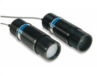 |
Typical Configuration of an Industrial
Infared Temperature Probe |
Automatic optical pyrometers, sensitized to measure in the infrared region, also are available. These instruments use an electrical radiation detector, rather than the human eye. This device operates by comparing the amount of radiation emitted by the target with that emitted by an internally controlled reference source. The instrument output is proportional to the difference in radiation between the target and the reference. A chopper, driven by a motor, is used to alternately expose the detector to incoming radiation and reference radiation. In some models, the human eye is used to adjust the focus. Figure 3-9 is a schematic of an automatic optical pyrometer with a dichroic mirror. Radiant energy passes through the lens into the mirror, which reflects infrared radiation to the detector, but allows visible light to pass through to an adjustable eyepiece. The calibrate flap is solenoid-operated from the amplifier, and when actuated, cuts off the radiation coming through the lens, and focuses the calibrate lamp on to the detector. The instrument may have a wide or narrow field of view. All the components can be packaged into a gun-shaped, hand-held instrument. Activating the trigger energizes the reference standard and read-out indicator.
Optical pyrometers have typical accuracy in the 1% to 2% of full scale range.
 |
| Figure 3-8 Optical Pyrometry By Visual comparison |
Fiber Optic Radiation
Although not strictly a class unto themselves, these devices use a light guide, such as a flexible transparent fiber, to direct radiation to the detector, and are covered in more detail in the chapter beginning on p. 43. The spectral response of these fibers extends to about 2 microns, and can be useful in measuring object temperatures to as low as 210°F (100°C). Obviously, these devices are particularly useful when it is difficult or impossible to obtain a clear sighting path to the target, as in a pressure chamber.
|
Top of Page
|
|
Next Chapter: IR Thermometers & Pyrometers Continued
|
|