Strain Gage Configurations
The bending beam sensor is one of the most popular load cell designs because of its simplicity and relatively low cost. It consists of a straight beam attached to a base at one end and loaded at the other. Its shape can be that of a cantilever beam, a "binocular" design (Figure 7-3A) or a "ring" design (Figure 7-3B). Strain gages are mounted on the top and bottom to measure tension and compression forces. Because the strain gages are vulnerable to damage, they are typically covered by a rubber bellows. The beam itself often is made of rugged alloy steel and protected by nickel plating.
Direct stress (or column/canister) load cells are essentially bending beam sensors mounted in a column inside a rugged, round container (Figure 7-3D). The beam sensor is mounted upright, with two of the four strain gages mounted in the longitudinal direction. The other two are oriented transversely. The column may be square, circular, or circular with flats machined on the sides to accommodate the strain gages.
The spring elements in a load cell (also called the "beam") can respond to direct stress, bending, or shear. They are usually called by names such as bending beam, shear beam, column, canister, helical, etc. (Figure 7-3). The two most popular designs for industrial weighing applications are the bending beam and the shear beam cells.
Figure 7-3: Load Cell
Spring Elements
In medical instrumentation, robotics, or similar low-load applications, smaller mini-beam sensors are available for measuring loads of up to about 40 pounds (18 kg). For loads up to 230 grams, the beam is made of beryllium copper, and for larger loads stainless steel is used. In this design, strain gages typically are protected by a urethane coating.
Ring or pancake designs are round and flat bending beam sensors consisting of bonded foil strain gages encapsulated in a stainless steel housing. The entire package resembles a flat pancake (Figure 7-3B). Compression-only sensors can be mounted in a protective, self-aligning assembly that limits load movement and directs the load toward the center of the pancake. Compression-tension designs have a threaded hole running completely through the center of the sensor. Stabilizing diaphragms are welded to the sensing load button.
Shear beam sensors measure the shear caused by a load. A bending beam sensor cannot measure shear, because shear stresses change across the cross section of the cell. In a shear sensor, the I-beam construction produces a uniform shear that can be accurately measured by strain gages. A shear beam sensor (Figure 7-3C) is provided with a pair of strain gages installed on each side of the I-beam, with grid lines oriented along the principal axes. Advantages of a shear beam sensor over a bending beam include better handling of side loads and dynamic forces, as well as a faster return to zero.
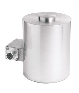
Typical high-capacity canister load cell,
If provided with a rocker assembly or with self-aligning strut bearings, a canister load cell can tolerate a certain amount of tank movement and is relatively insensitive to the point of loading. Also, the canister protects the strain gages from physical and environmental damage. Canister cells range in size from 1-1/2 in. diameter "studs" with 100-500 lb. capacity to 6-1/2 in. diameter compression cells suitable for weighing trucks, tanks, and hoppers up to 500,000 lb.
Helical load cells are better able to handle off-axis loading than are canister-type compression cells (Figure 7-3E). The operation of a helical load cell is based on that of a spring. A spring balances a load force by its own torsional moment. The torsional reaction travels from the top of the helix to the bottom. By measuring this torsional moment with strain gages mounted on the spring, a helical load cell can provide reasonably accurate load measurement without the need for expensive mounting structures. Forces caused by asymmetrical or off-axis loading have little effect on the spring, and the strain gage sensors can measure both tension and compression forces.
A helical load cell can be mounted on rough surfaces, even where the upper and lower surfaces are not parallel, and total error can still remain within 0.5%. The helical load cell also is resistant to shock and overload (it can handle a thousandfold overload), making it ideal for force or load measurements on vehicle axles, seats, or in forklift applications.
Button and flat washer bonded strain gage load cells are available in sizes from 1/4 to 1-1/2 in. diameter. The smallest sensors are available only in compression styles, but some of the larger cells have threaded holes for also measuring tension. While most of the tiny sensors handle up to about 200 lb., some are capable of measuring up to 50,000 lb. Because these little cells have no fixtures or flexures, off-axis loading and shifting loads cannot be tolerated.
On the other hand, button and flat washer load cells are extremely convenient and easy to use. Even the smallest sensor is built of stainless steel, has a built in, full four-arm Wheatstone bridge, and can measure up to 200 lb. at temperatures up to 1500¡F.
| References & Further Reading | |
| Omegadyne Pressure, Force, Load, Torque Databook, Omegadyne, Inc., 1996. | |
| The Pressure, Strain, and Force Handbook, Omega Press LLC, 1996. | |
| Elements of Electronic Instrumentation and Measurements, 3rd Edition, Joseph J. Carr, Prentice Hall, 1996. | |
| Industrial Control Handbook, E.A. Parr, Butterworth-Heinemann, 1995. | |
| Instrument Engineers' Handbook, Bela Liptak, CRC Press LLC, 1995. | |
| Process/Industrial Instruments and Controls Handbook, 4th Edition, Douglas M. Considine, McGraw-Hill, 1993. | |
| Van Nostrand's Scientific Encyclopedia, Douglas M. Considine and Glenn D. Considine, Van Nostrand, 1997. | |
| Weighing and Force Measurement in the '90s, T. Kemeny, IMEKO TC Series, 1991. |